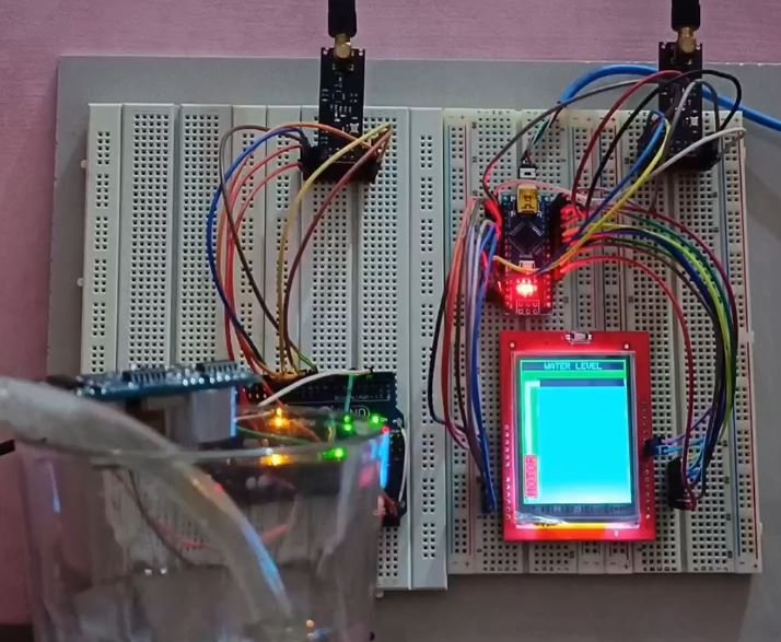
You may have seen many Wired and Wireless Water Level Indicators that would provide range up to 100 to 200 meters. But in this blog, you are going to see a Long Range Wireless Water Level Indicator that can provide a theoretical range up to 1 km {Edit – many users getting very less range, so it is recommended to test project on breadboard first and if it works for your application, then go for PCB version}. And this prototype has a LOW level and Full Level Alarm. And definitely, it works for a real water tank.
Step 1: Material Required For Wireless Water Level Indicator


As it’s a wireless project you need to have transmitter and receiver. And here are the components required for Transmitter (Refer circuit diagram for more details):
RJ45 Ethernet Cable,
RJ45 female connector,
Resistors,
Transistors,
Capacitor,
Female header strips,
Arduino Nano
Long Range RF Module (NRF24L01+PA+LNA) and
A custom made PCB.
For the receiver (Refer circuit diagram for more details):
Resistor
Transistor
Capacitor
Buzzer
Female header strips
Long Range RF module (NRF24L01+PA+LNA)
Arduino Nano
2.2’’ LCD display (ILI9225) and
A custom made PCB.
Step 2: Circuit and PCB Design of Wireless Water Level Indicator
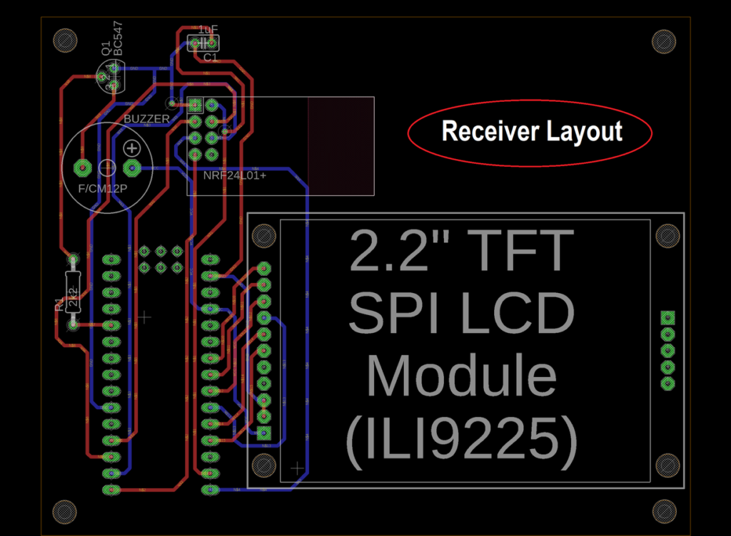


Autodesk Eagle is used to design Circuit and layout for transmitter and receiver. I was having trouble searching Eagle Library for the LCD display, so I created a custom library for it. You can refer this video that shows How to ‘’Create A Custom Library In Autodesk EAGLE’’: https://youtu.be/FWbGdwL3-OU
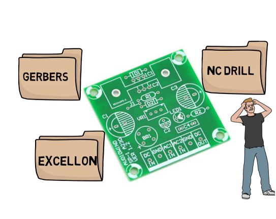
Step 3: Gerber Export

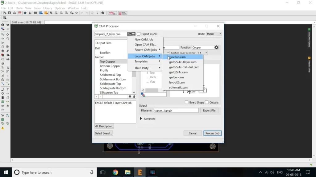
After completing design it’s time to export Gerber File. PCB manufacturer needs this file to produce PCB. To export Gerber File from Autodesk Eagle Design:
For Transmitter:
Click on File,
Cam Processor,
Load Job file,
Load cam jobs,
gerb274x.cam and
then process Job.
Now we need to repeat the process for excellon.cam. Make sure you save both process file in the same folder.
Click on File,
Cam Processor,
Load Job file,
Load cam jobs,
excellon.cam and
then process Job.
Combining both process gerb274x.cam and excellon.cam files will give u a Gerber file. Select files produced by these processes and make .zip file.
Now repeat the whole thing for receiver unit.
Step 4: Order PCB Online
After exporting Gerber files for transmitter and Receiver, I visited jlcpcb.com. JLCPCB is offering first order for just $2 (10 PCBs) and first shipping free. For 2nd order, you need to pay $5.
Step 5: Soldering


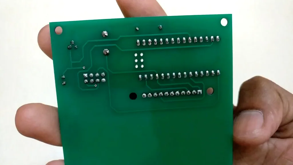

I always prefer using Female strips instead of directly soldering main components. So they can be reused when needed. So before soldering, I prepared some strips and then did the soldering. I tried to keep it as clean as possible. Always refer PCB layout for inserting components.
Step 6: Uploading Program
Now it’s time to upload Arduino code to Transmitter and Receiver. Before uploading code to arduino, make sure to install arduino libraries (RF24-master and UTFT) if not aready installed.
Transmitter code:
#include <SPI.h>
#include <RF24.h>

RF24 radio(9, 10); // CE, CSN
const byte addresses[][6] = {"00001"};

const uint8_t level_pins[] = { 2, 3, 4, 5, 6, 7, 8 };
const uint8_t num_level_pins = sizeof(level_pins);
uint8_t level_states[num_level_pins];

void setup()
{
  int i = num_level_pins;
  while (i--)
  {
    pinMode(level_pins[i], INPUT);
  }
  Serial.begin(9600);
  radio.begin();
  radio.setRetries(15, 15);
  radio.setDataRate(RF24_1MBPS);
  radio.openWritingPipe(addresses[0]); // 00001
  radio.setPALevel(RF24_PA_HIGH);
  radio.enableDynamicPayloads();
}

void loop()
{
  int i = num_level_pins;
  bool different = false;
  while (i--)
  {
    uint8_t state = ! digitalRead(level_pins[i]);
    if ( state != level_states[i] )
    {
      different = true;
      level_states[i] = state;
    }
  }

  if ( different )
  {
    Serial.println("Now sending...");
retry:    bool ok = radio.write( level_states, num_level_pins );
    Serial.print("Level States: ");
    Serial.print(level_states[0]);
    Serial.print(" , ");
    Serial.print(level_states[1]);
    Serial.print(" , ");
    Serial.print(level_states[2]);
    Serial.print(" , ");
    Serial.println(level_states[3]);
    Serial.print(" , ");
    Serial.print(level_states[4]);
    Serial.print(" , ");
    Serial.print(level_states[5]);
    Serial.print(" , ");
    Serial.println(level_states[6]);
    if (ok)
      Serial.println("Sent\n\r");
    else
    { Serial.println("Failed\n\r");
      goto retry;
    }
  }
  delay(20);
}
Receiver Code:
#include <SPI.h>
#include <RF24.h>

RF24 radio(9, 10); // CE, CSN
const byte addresses[][6] = {"00001"};

int Buzz = 2;

const uint8_t level_pins[7];
const uint8_t num_level_pins = sizeof(level_pins);
uint8_t level_states[num_level_pins];

#include <UTFT.h>
UTFT myGLCD(QD220A, A2, A1, A5, A4, A3); // SDI,CLK,CS,RST,RS
int LED = A0;
extern uint8_t BigFont[];
extern uint8_t SmallFont[];
extern uint8_t SevenSegNumFont[];

void setup()
{
  pinMode(LED, OUTPUT);
  digitalWrite(LED, HIGH);
  pinMode(Buzz, OUTPUT);
  digitalWrite(Buzz, LOW);
  myGLCD.InitLCD(0);
  myGLCD.clrScr();
  myGLCD.setFont(BigFont);
  myGLCD.setColor(VGA_TEAL);
  myGLCD.print("Wireless", CENTER, 50, 360);
  myGLCD.print("Water", CENTER, 80, 360);
  myGLCD.print("Level", CENTER, 110, 360);
  myGLCD.print("Indicator", CENTER, 140, 360);
  delay(1000);

  myGLCD.clrScr();
  myGLCD.print("Water Level", 0, 0, 360);
  myGLCD.setColor(VGA_NAVY);

  myGLCD.fillRect(0, 217, 175, 219);
  myGLCD.fillRect(0, 20, 2, 216);
  myGLCD.fillRect(173, 20, 175, 219);

  myGLCD.drawLine(0, 191, 175, 191);
  myGLCD.drawLine(0, 163, 175, 163);
  myGLCD.drawLine(0, 135, 175, 135);
  myGLCD.drawLine(0, 107, 175, 107);
  myGLCD.drawLine(0, 79, 175, 79);
  myGLCD.drawLine(0, 51, 175, 51);
  myGLCD.drawLine(0, 23, 175, 23);

  int i = num_level_pins;
  Serial.begin(9600);
  radio.begin();
  radio.setRetries(15, 15);
  radio.setDataRate(RF24_1MBPS);
  radio.openReadingPipe(1, addresses[0]); // 00001
  radio.setPALevel(RF24_PA_HIGH);
  radio.enableDynamicPayloads();
  radio.startListening();
}

void loop()
{
L1:  while (!radio.available());
  radio.read( level_states, num_level_pins );

  int i = num_level_pins;
  while (i--)
  {
    if ( level_states[6])
    {
      Serial.println("Level 7");
      myGLCD.setColor(VGA_TEAL);
      myGLCD.fillRect(3, 24, 172, 50);
      for (int k = 0; k <= 5; k++)
      {
        myGLCD.setColor(VGA_GREEN);
        myGLCD.print("FULL", CENTER, 28, 360);
        digitalWrite(Buzz, HIGH);
        delay(50);
        myGLCD.setColor(VGA_TEAL);
        myGLCD.print("FULL", CENTER, 28, 360);
        digitalWrite(Buzz, LOW);
        delay(50);
      }
      goto L1;
    }
    if ( level_states[5])
    {
      Serial.println("Level 6");
      myGLCD.setColor(VGA_TEAL);
      myGLCD.fillRect(3, 52, 172, 78);
      myGLCD.setColor(VGA_BLACK);
      myGLCD.fillRect(3, 24, 172, 50);
      goto L1;
    }
    if ( level_states[4])
    {
      Serial.println("Level 5");
      myGLCD.setColor(VGA_TEAL);
      myGLCD.fillRect(3, 80, 172, 106);
      myGLCD.setColor(VGA_BLACK);
      myGLCD.fillRect(3, 52, 172, 78);
      goto L1;
    }
    if ( level_states[3])
    {
      Serial.println("Level 4");
      myGLCD.setColor(VGA_TEAL);
      myGLCD.fillRect(3, 108, 172, 134);
      myGLCD.setColor(VGA_BLACK);
      myGLCD.fillRect(3, 80, 172, 106);
      goto L1;
    }
    if ( level_states[2])
    {
      Serial.println("Level 3");
      myGLCD.setColor(VGA_TEAL);
      myGLCD.fillRect(3, 136, 172, 162);
      myGLCD.setColor(VGA_BLACK);
      myGLCD.fillRect(3, 108, 172, 134);
      goto L1;
    }
    if ( level_states[1])
    {
      Serial.println("Level 2");
      myGLCD.setColor(VGA_TEAL);
      myGLCD.fillRect(3, 192, 172, 216);
      myGLCD.fillRect(3, 164, 172, 190);
      myGLCD.setColor(VGA_BLACK);
      myGLCD.fillRect(3, 136, 172, 162);
      goto L1;
    }
    if ( level_states[0])
    {
      Serial.println("Level 1");
      myGLCD.setColor(VGA_TEAL);
      myGLCD.fillRect(3, 192, 172, 216);
      myGLCD.setColor(VGA_BLACK);
      myGLCD.fillRect(3, 164, 172, 190);
      for (int k = 0; k <= 4; k++)
      {
        myGLCD.setColor(VGA_RED);
        myGLCD.print("LOW", CENTER, 196, 360);
        digitalWrite(Buzz, HIGH);
        delay(50);
        myGLCD.setColor(VGA_TEAL);
        myGLCD.print("LOW", CENTER, 196, 360);
        digitalWrite(Buzz, LOW);
        delay(50);
      }
      goto L1;
    }
  }
  delay(5);
}
Step 7: Identifying VCC and Level pins from ethernet wire and Testing


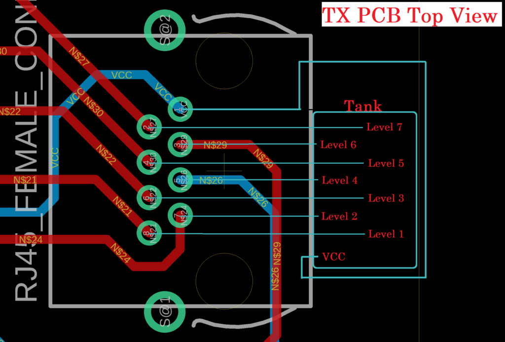
After uploading code I prepared testing probe by cutting one end of Ethernet Cable. As this cable consists of total 8 wires. One wire will be used as VCC pin and rest as a Water Level pins. So total Seven Levels.
Identify different level pins and VCC pin by checking continuity between RJ45 connector solder pins on PCB and ethernet wires with the help of the following image. After successful identification, follow the following steps for final testing.
- Make proper setup before turning Tx and Rx ON.
- Turn ON receiver, wait till display is ready ( if the display is not turning ON, reset the Rx from the main power source or Reset Button available on Arduino Nano).
- Fill the complete tank, then turn ON the transmitter. Initially the FULL level will light up with a buzzer. Wait till buzzer stops.
- Then take water out of the tank slowly observing degradation in levels.
- Lastly, you will observe a LOW level with a buzzer (wait till buzzer stops).
- Now you can fill the tank gradually see the level changing from top to bottom and vice versa.
- Make sure not to change water level when the buzzer is active, as written code in Arduino Nano will wait for Buzzer to stop then it will update receiving levels from the transmitter, While writing code, I assumed that it takes time to add or remove water to/from the tank, so buzzer is driven by microcontroller only which will take time. But this should not be the problem in a real water tank.
I tested the circuitry in real water tank also and it worked fine.
If you liked this blog, don’t forget to subscribe my Youtube Channel https://goo.gl/CGHKT1

Krishna has been a life-saver with this project from start to finish! He put this together way back in 2018, I stumbled on it in 2023 after we installed an irrigation tank at our Farm which is in a remote part of the property. Without spending thousands of dollars on a manufactured system, I wanted to give a try and building a custom solution based on the efforts of someone like Krishna.
Last year I got all the components together, I’m now finally getting them soldered in place and the sensor, transmitter, and receiver in place at the Farm. He’s been able to walk me through a number of the confusing parts for me. His work is well detailed in the YouTube video as well as here…I’m just totally new to soldering circuit boards and uploading code to PCB’s.
I will drop in another note once I get this finished and up and running in the next few weeks. Great work Krishna…thanks!
Arduino: 1.8.18 (Windows 10), Board: “Arduino Nano, ATmega328P”
C:\Users\Akhil v\Documents\Arduino\sketch_jul05a\sketch_jul05a.ino:9:15: warning: uninitialized const ‘level_pins’ [-fpermissive]
const uint8_t level_pins[7];
^~~~~~~~~~
C:\Users\Akhil v\Documents\Arduino\sketch_jul05a\sketch_jul05a.ino: In function ‘void setup()’:
C:\Users\Akhil v\Documents\Arduino\sketch_jul05a\sketch_jul05a.ino:36:42: warning: ISO C++ forbids converting a string constant to ‘char*’ [-Wwrite-strings]
myGLCD.print(“Wireless”, CENTER, 50,360);
^
C:\Users\Akhil v\Documents\Arduino\sketch_jul05a\sketch_jul05a.ino:37:39: warning: ISO C++ forbids converting a string constant to ‘char*’ [-Wwrite-strings]
myGLCD.print(“Water”, CENTER, 80,360);
^
C:\Users\Akhil v\Documents\Arduino\sketch_jul05a\sketch_jul05a.ino:38:40: warning: ISO C++ forbids converting a string constant to ‘char*’ [-Wwrite-strings]
myGLCD.print(“Level”, CENTER, 110,360);
^
C:\Users\Akhil v\Documents\Arduino\sketch_jul05a\sketch_jul05a.ino:39:44: warning: ISO C++ forbids converting a string constant to ‘char*’ [-Wwrite-strings]
myGLCD.print(“Indicator”, CENTER, 140,360);
^
C:\Users\Akhil v\Documents\Arduino\sketch_jul05a\sketch_jul05a.ino:43:41: warning: ISO C++ forbids converting a string constant to ‘char*’ [-Wwrite-strings]
myGLCD.print(“Water Level”, 0, 0,360);
^
C:\Users\Akhil v\Documents\Arduino\sketch_jul05a\sketch_jul05a.ino: In function ‘void loop()’:
sketch_jul05a:67:57: error: void value not ignored as it ought to be
done = radio.read( level_states, num_level_pins );
^
C:\Users\Akhil v\Documents\Arduino\sketch_jul05a\sketch_jul05a.ino:80:50: warning: ISO C++ forbids converting a string constant to ‘char*’ [-Wwrite-strings]
myGLCD.print(“FULL”, CENTER, 28,360);
^
C:\Users\Akhil v\Documents\Arduino\sketch_jul05a\sketch_jul05a.ino:84:50: warning: ISO C++ forbids converting a string constant to ‘char*’ [-Wwrite-strings]
myGLCD.print(“FULL”, CENTER, 28,360);
^
C:\Users\Akhil v\Documents\Arduino\sketch_jul05a\sketch_jul05a.ino:140:50: warning: ISO C++ forbids converting a string constant to ‘char*’ [-Wwrite-strings]
myGLCD.print(“LOW”, CENTER, 196,360);
^
C:\Users\Akhil v\Documents\Arduino\sketch_jul05a\sketch_jul05a.ino:144:50: warning: ISO C++ forbids converting a string constant to ‘char*’ [-Wwrite-strings]
myGLCD.print(“LOW”, CENTER, 196,360);
^
exit status 1
void value not ignored as it ought to be
receiver code error sir please help
Code has been updated, try compiling updated code. But make sure to install Arduino libraries provided in step 6 before compiling the codes.
If you are unable to add libraries to Arduino. Go to Arduino program files and search for libraries folder and paste downloaded library after unzipping it.
Sir, I checked the new code .I think there is an error ..The receiver always shows level full when the transmitter is on..
sir, I checked the new code .I think there is an error ..The receiver always shows level full when the transmitter is on..